The Keyboard
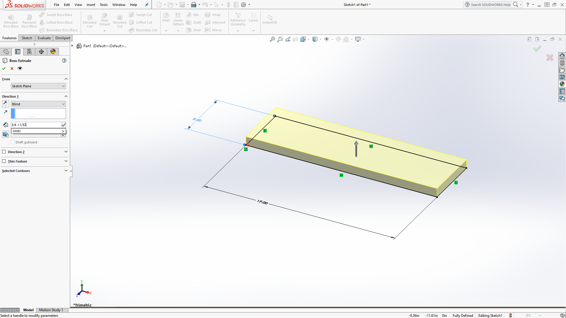
We made our table in the last post, so now we'll begin working on our keyboard. It will have a fairly simple design, with 3 grids of keys for the primary typing section, the number pad, and the Function keys. To start with though, we need to create a place to put those keys on. For this, we need a raised platform with some fancy curved corners. We'll start with a simple box: a rectangle which is 17 inches wide and 5 inches tall extruded three quarters of an inch, plus the 1/32 to fill in the dip from before. Fortunately for us, Solidworks can do math, so we just need to enter "3/4+1/32" as our height.
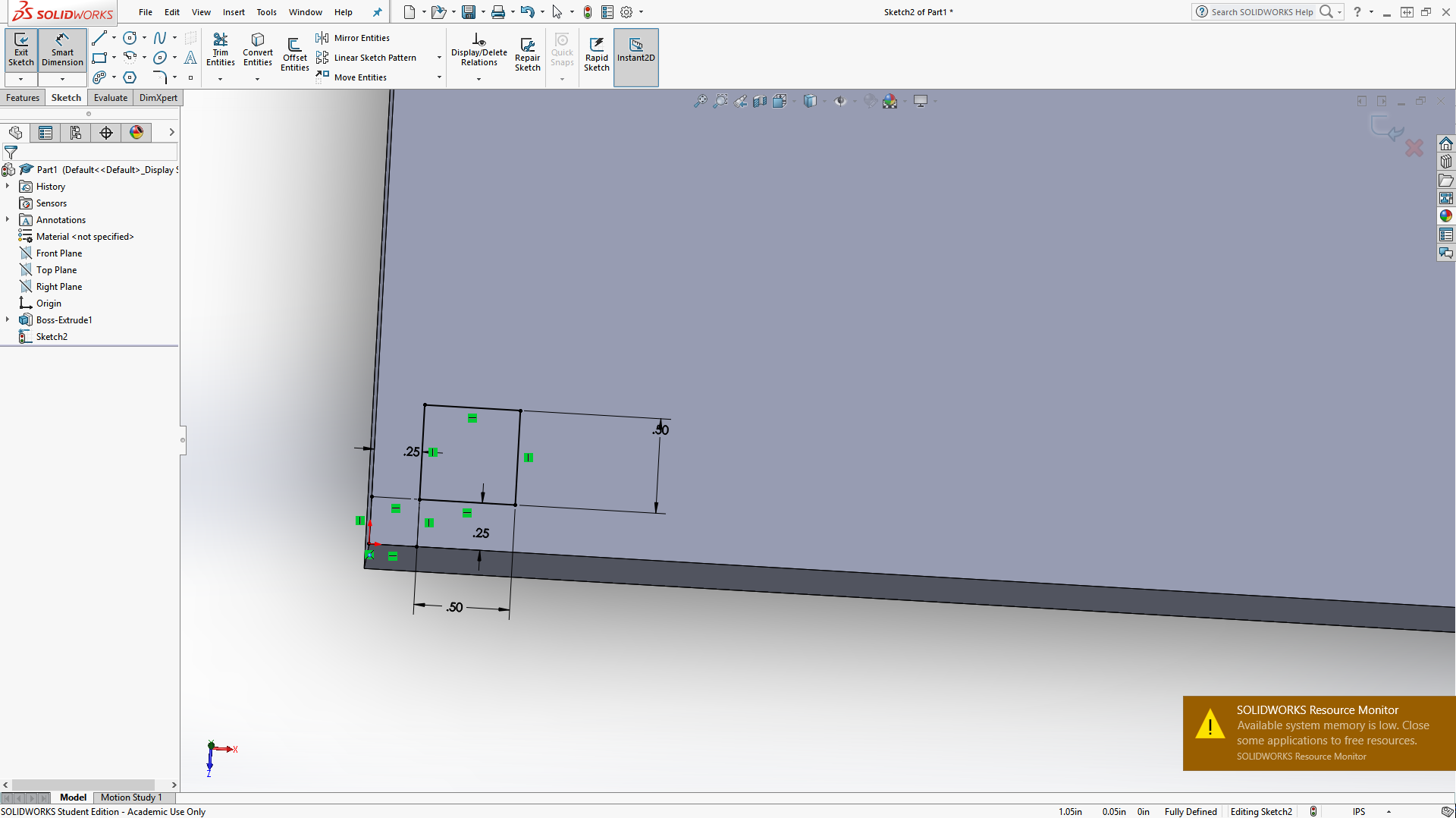
Once we have our box by clicking on the green check mark, we can begin on the keys. These will start with a square .25 by .25 inches up and right from the bottom left corner. Set those lines to For Construction, and then make a .5x.5 square on the top right of that to be our first key.
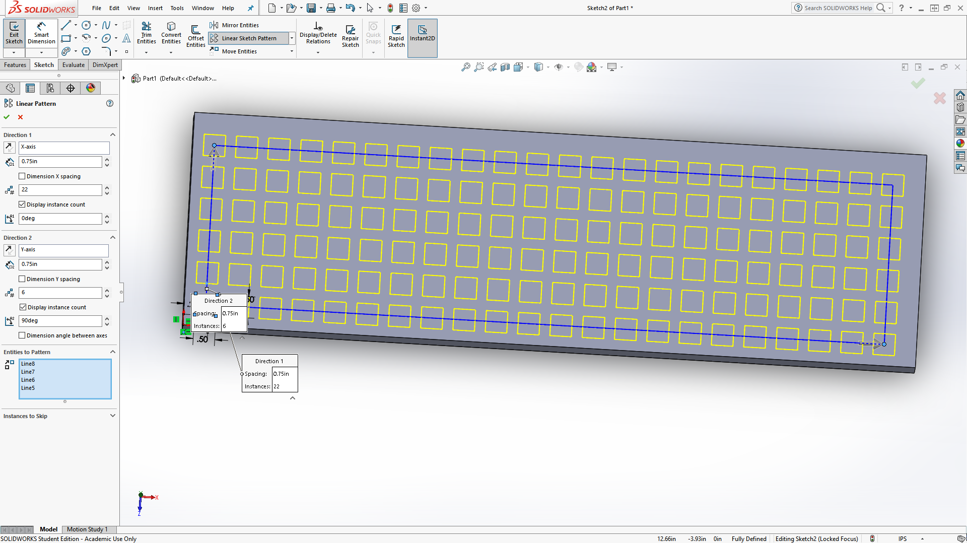
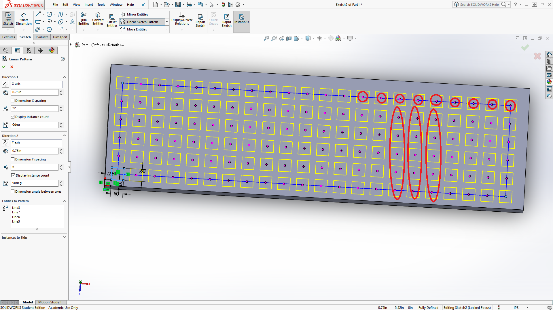
Of course, we want lots of keys. We'll use a Linear Pattern to make a grid of 6x22 squares. To do such, click on the "Linear Sketch Pattern" and, under the "Entities to Pattern" box, select the lines from the .5 x .5 square. Under Direction 1, set D1 to .75 and # to 22. Under Direction 2, set D2 to .75 and # to 6. If it looks like the image below, you're all set. If the yellow squares are rotated 90 degrees, switch the # entries. If your yellow squares currently go the opposite direction, you may need to switch the directions with the "Reverse Direction" buttons.
Now, we don't want all of those keys, so we'll click the text "Instances to Skip." Here you want to click on the circles I outlined below. After that, click the green check.
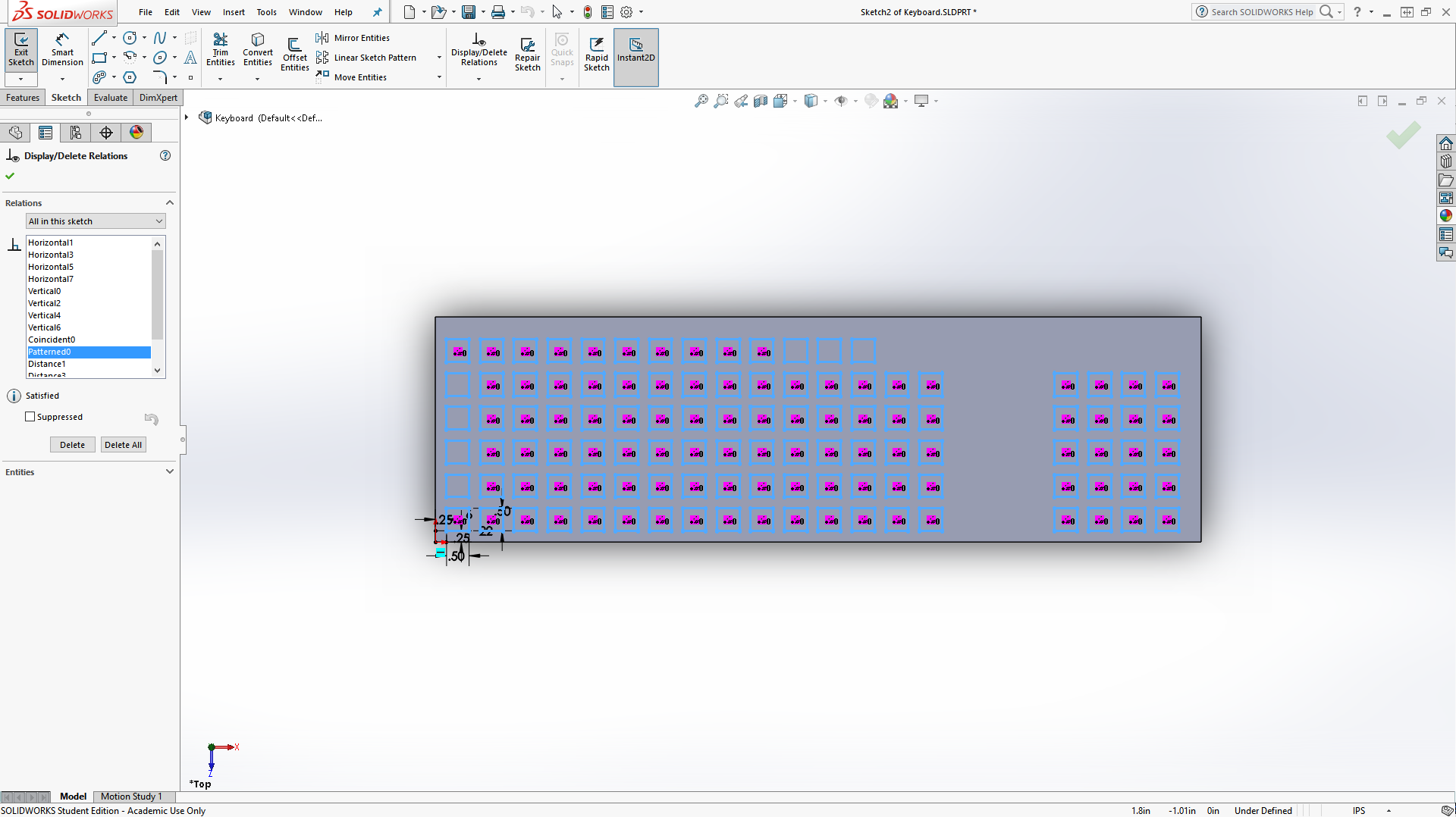
Before we can start moving and joining squares, make sure you are above the keyboard and the keyboard's sides are nearly horizontal and vertical. Also, we need to delete a relation by clicking on "Display/Delete Relations" and scrolling to find and select a relation named "Pattern0" or possibly "Patterned1" and pressing delete.
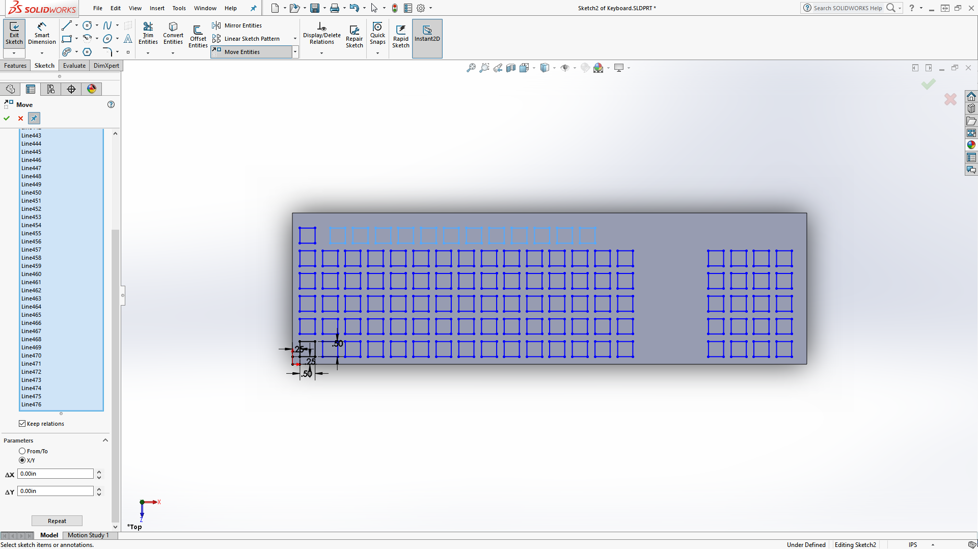
Now, select all of the squares on the top row except the furthest left one and click the Move Entities to move the squares right .5 inches. Do this by selecting the "X/Y" parameter and finding the right x/y value to set to .5 or -.5 so that it matches as shown below.
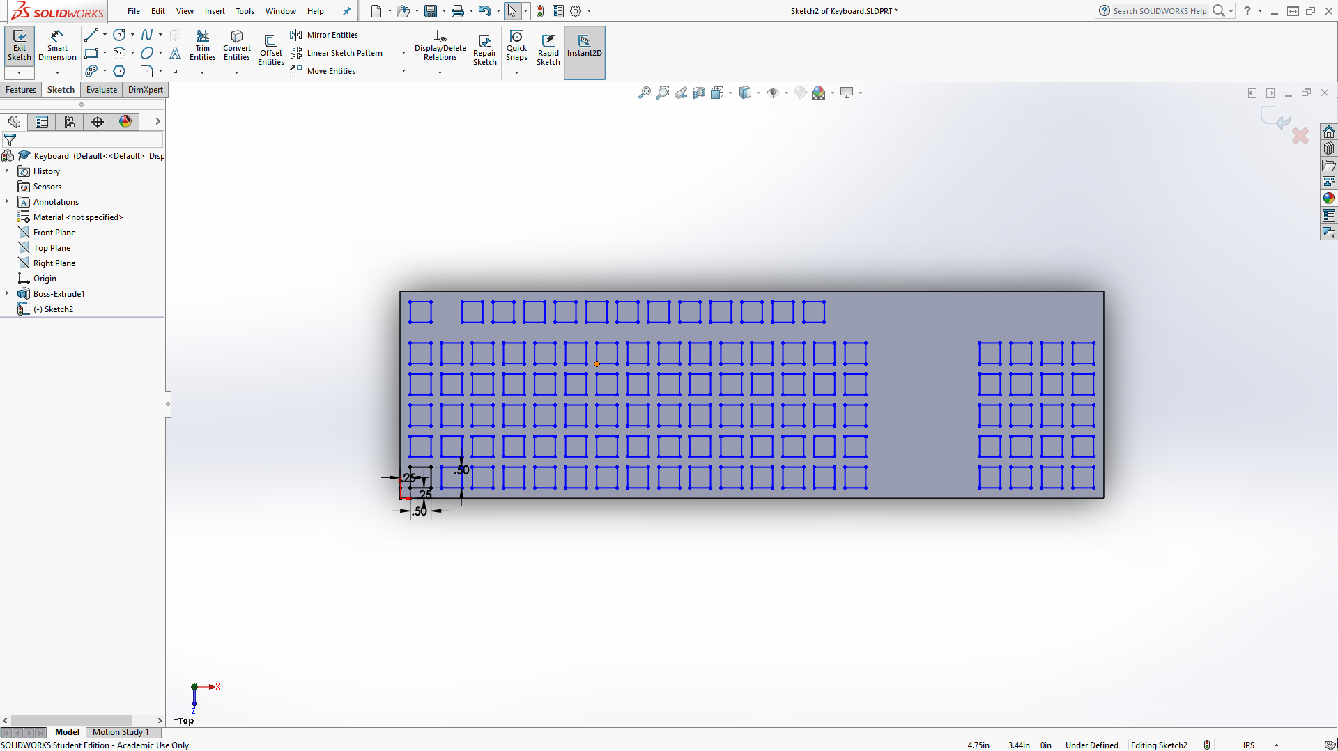
Using the method described above, move the entire top row up .25 inches and the number pad right .25 inches. Your keyboard should look as below.

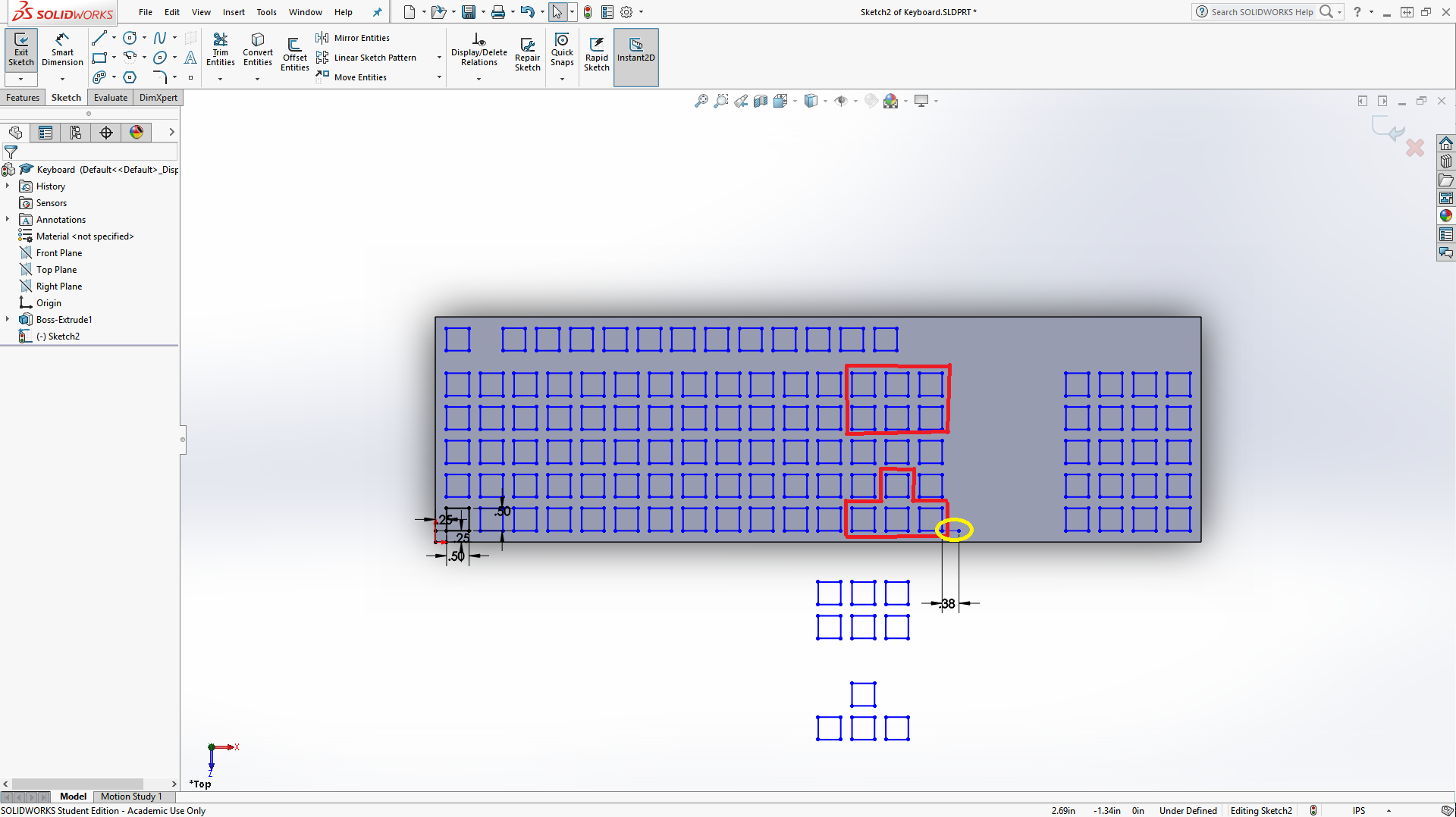
Now, copy the highlighted shapes and paste them from the keyboard. We'll move them later. To start, make the circled line, which is 3/8 long. (It should be "For Construction")
Now move the bottom right corner of the keys that you copied off the keyboard to the end of that line by using the Move tool but selecting the squares, selecting the "From/To" option, clicking on "Start Point", clicking on the bottom left corner, and then clicking the end of the line.
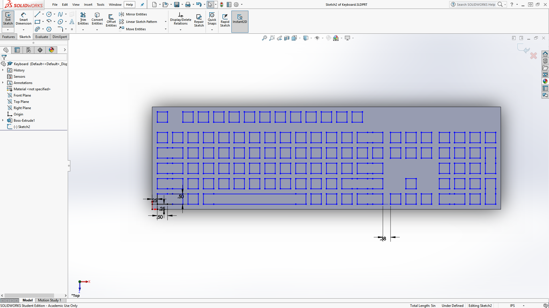
Finally, use lines to connect certain squares as shown below and delete the vertical lines in your new rectangles. When complete, extrude the keys up .375 inches. This may take some time, but be patient and it will most likely eventually work.
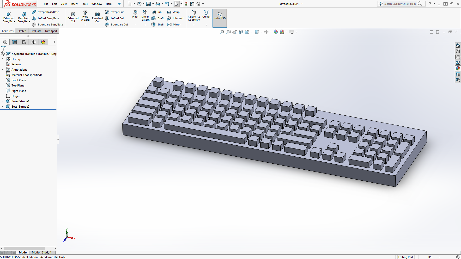
Now that our keys are in place, round the corners with the fillet tool found in the toolbar. By clicking on this tool, we can round sharp corners. Click the 4 short edges to select them for rounding, and set the radius to .25. Yellow lines should show a preview of how the object will look after filleting.
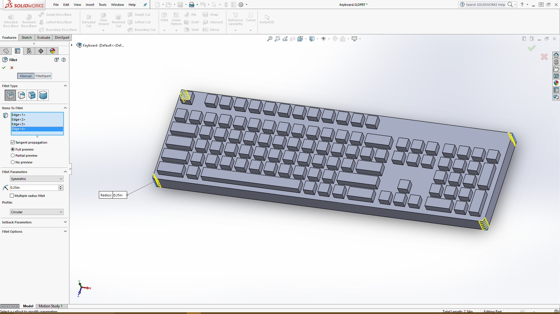
Now, just confirm the fillet and set the material/appearance to a nice black plastic (or some other color, I suppose) and the keyboard is done! (Do make sure you have saved at some point, and at the end)
Posted 5:13pm 7/12/17
